With the rapid development of offshore wind farms, oil and gas platforms, and underwater interconnection projects, the demand for robust and reliable submarine cable systems has surged. Submarine cables are essential for transmitting power, control, monitoring, and communication signals between offshore facilities and onshore substations—or even between islands, countries, and continents.
Submarine cables are specially designed to operate in harsh underwater environments, and must comply with international standards such as IEC 60288. They are engineered to withstand:
Rugged seabeds (rocky terrain, steep slopes)
Marine life that may damage insulation or sheathing
Fishing trawls, which pose more risk than marine fauna
Natural disasters like tsunamis, underwater earthquakes, or volcanic activity
Seabed and ambient temperature
Required burial depth and shore approach protection
Cable axial spacing
Thermal resistivity of seabed and land
Cable route length
Water depth
Voltage class (typically 3.6/6 kV up to 525 kV AC, or even higher for HVDC systems)
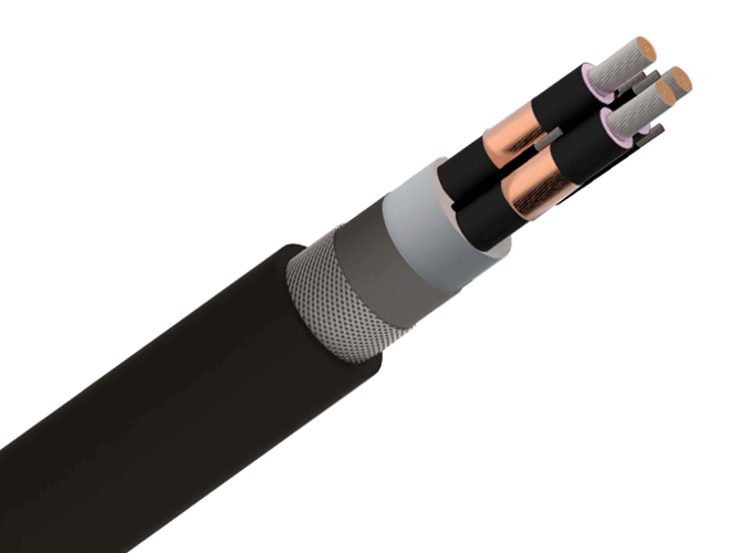
Depending on voltage and application, cables may be single-core or three-core, with cross-sections reaching up to 2500 mm² in some HVDC designs.
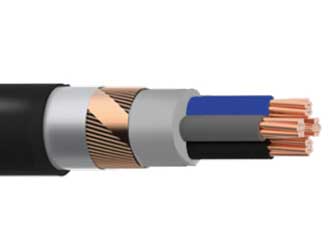
| Component | Description |
| Conductor | High-purity copper or aluminum; can be water-blocked for deep-sea use |
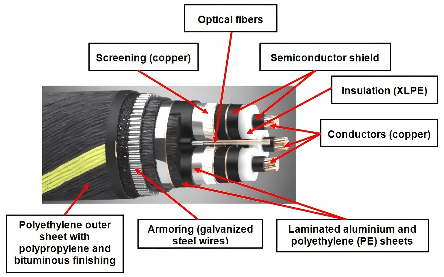
| Insulation | XLPE, EPR, or MIND (mass-impregnated paper insulation) |
| Screening | Copper wires/tapes and lead sheath (if needed for water resistance) |
| Armouring | Galvanized steel wires or non-magnetic armouring (e.g., aluminum for single-core cables to prevent heating from eddy currents) |
| Outer Protection | PVC or PE sheath; may include polypropylene yarns or jute wrapping for added mechanical protection |
Three-core submarine cables may include optical fiber elements for communication. When using single-core cables, separate optical fiber submarine cables may be required.
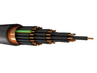
Umbilical cables can include power, optical fiber, and control lines in a single structure—ideal for subsea processing systems.
Some umbilicals also integrate steel tubes for fluid transfer (low- or high-pressure lines).
Before cable laying begins, comprehensive planning and seabed studies are required:
Routing selection using updated marine charts
Seabed surveys for:
Bathymetry (depth)
Topography
Lithology (rock/soil type)
Environmental factors (salinity, temperature, pH)
Seismic and marine activity risks (e.g., currents, tsunamis)
Burial assessment:
Evaluate burial needs
Use hydro jet trenchers where necessary
Monitor sensitive areas via ROVs (Remotely Operated Vehicles)
Cable laying is typically carried out by dedicated cable-laying vessels, equipped with precision deployment systems, and supported by robotic tools for accurate placement on the seabed.
For long-distance routes or in the event of cable damage, high-reliability joints are necessary.
Performed under controlled environments, ideally at the manufacturer's factory
Must pass insulation, dielectric, ultrasonic, and radiographic testing
Designed to resist hydrostatic pressure, mechanical stress, and long-term corrosion
2Y-1.jpg)